Industrial automation for material handling lines
Control design connects the operating sequence of the line with actual measurements and equipment status. The scope includes operator interfaces, control panels, interlocks and the signals agreed for the project.
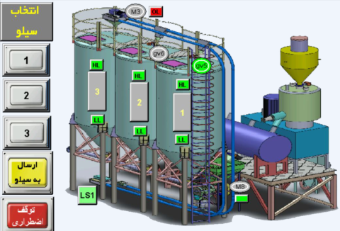
Automation starts with a process description and a list of inputs and outputs. Sensors, motors, valves and weighing devices are reviewed alongside manual operation, automatic sequences and the required response to faults.
Technical selection
| Operating sequence | Start, feeding, destination selection, discharge, normal stop and fault response. |
|---|---|
| Measurements | Vessel level, weight, equipment status and process signals required by the application. |
| Operator interface | Equipment overview, setpoints, operating modes, alarms and accessible status information. |
| Control panel | Power and control circuits, motor protection, field terminals and electrical drawings. |
| Integration | Available PLC or supervisory system interfaces, signal type and communication requirements. |
Signals, operating modes and commissioning
| Field signals | Define the level switches, weighing signals, motor status and valve feedback in an I/O list. Confirm the signal type and electrical interface for each device. |
|---|---|
| Operator functions | Agree manual and automatic operation, destination selection, displayed status, setpoints and alarm acknowledgement for the line. |
| Sequence checks | Review the conditions for starting, feeding, discharging, normal stopping and responding to a fault against the approved sequence. |
| Handover records | Keep the final I/O list, electrical drawings, parameter backups and operator instructions together with the commissioning results. |
Installation & maintenance
- Check field wiring, sensor direction and valve feedback against the agreed I/O list.
- Verify interlocks and operating sequences during commissioning under defined conditions.
- Keep electrical drawings, parameter backups and operator instructions with the project records.
HMI examples from material handling projects
These screens illustrate different arrangements for conveying, weighing, dosing and destination selection. Open an image to inspect the complete process view; the operating sequence and displayed signals are defined for each project.
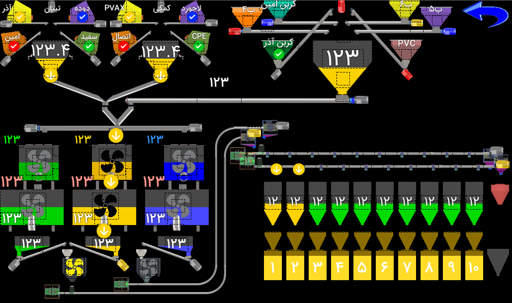
Raw-material and additive hoppers, weighing and mixing stages, and conveying routes to numbered feed hoppers.
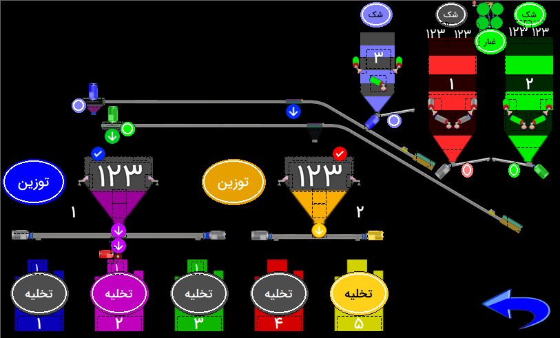
Two weighing hoppers, receiving vessels and conveying routes to five discharge points, with equipment status beside the process route.
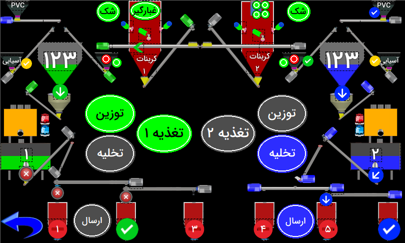
PVC, carbonate and regrind reception, with feeding, weighing, discharge and dispatch stages shown in one view.
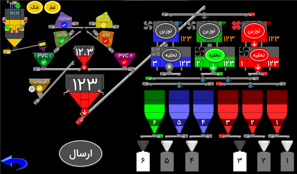
PVC and additive hoppers, three weighing and discharge routes, and distribution to six numbered vessels.
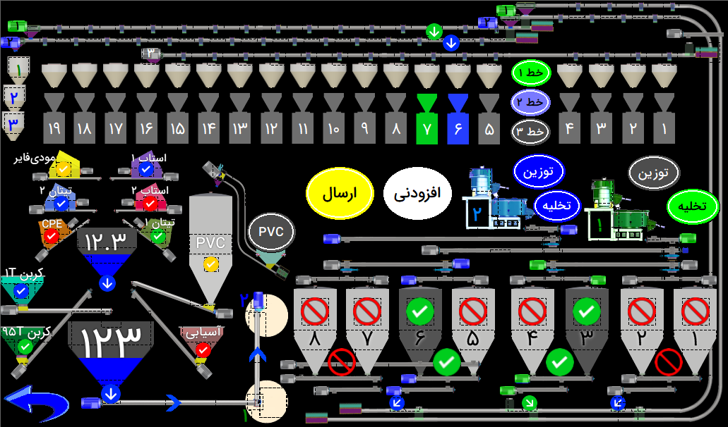
Destination hoppers, conveying lines and additive weighing, with symbols showing whether routes are enabled or stopped.
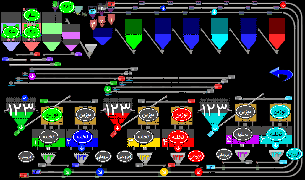
Upstream storage and three operating groups, showing weighing, additive handling, discharge and the routes connecting them.
Earlier control interface example
Request a technical review
Send the application, operating conditions, dimensions and available drawings or photographs. State any information that is still unknown so the technical review can address it.