Rotary paddle level switches
A small drive rotates a paddle. Material reaching the paddle resists its rotation and changes the switching state for level indication or a control interlock.
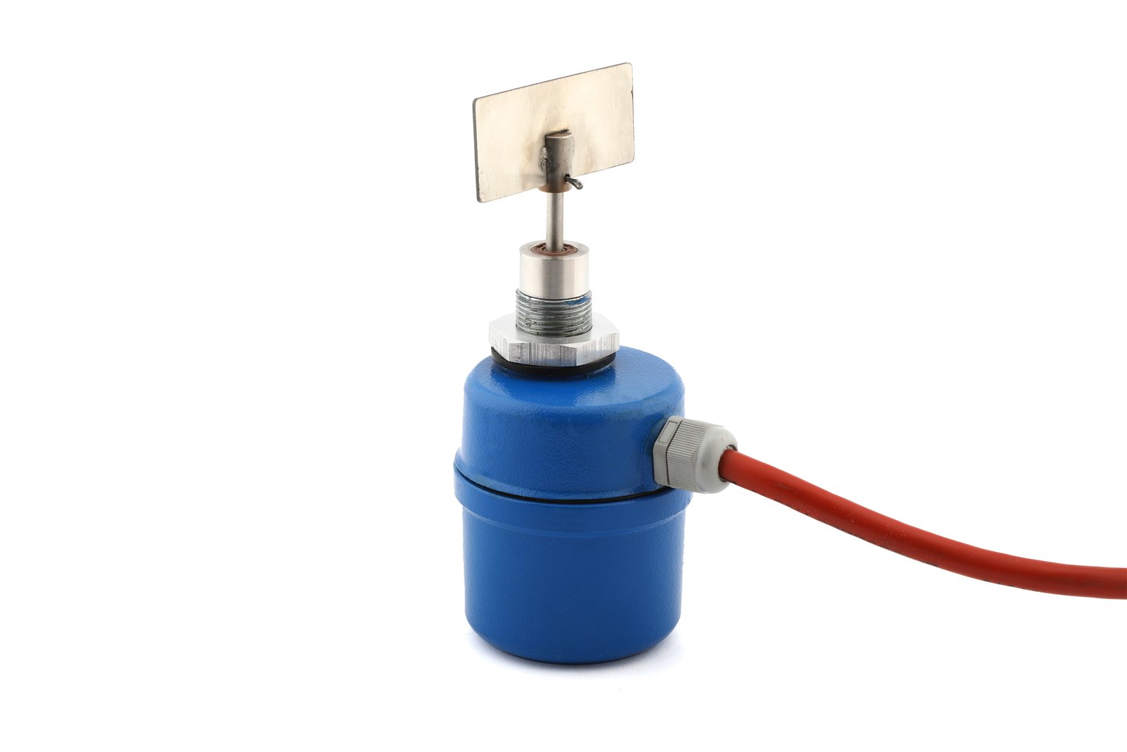
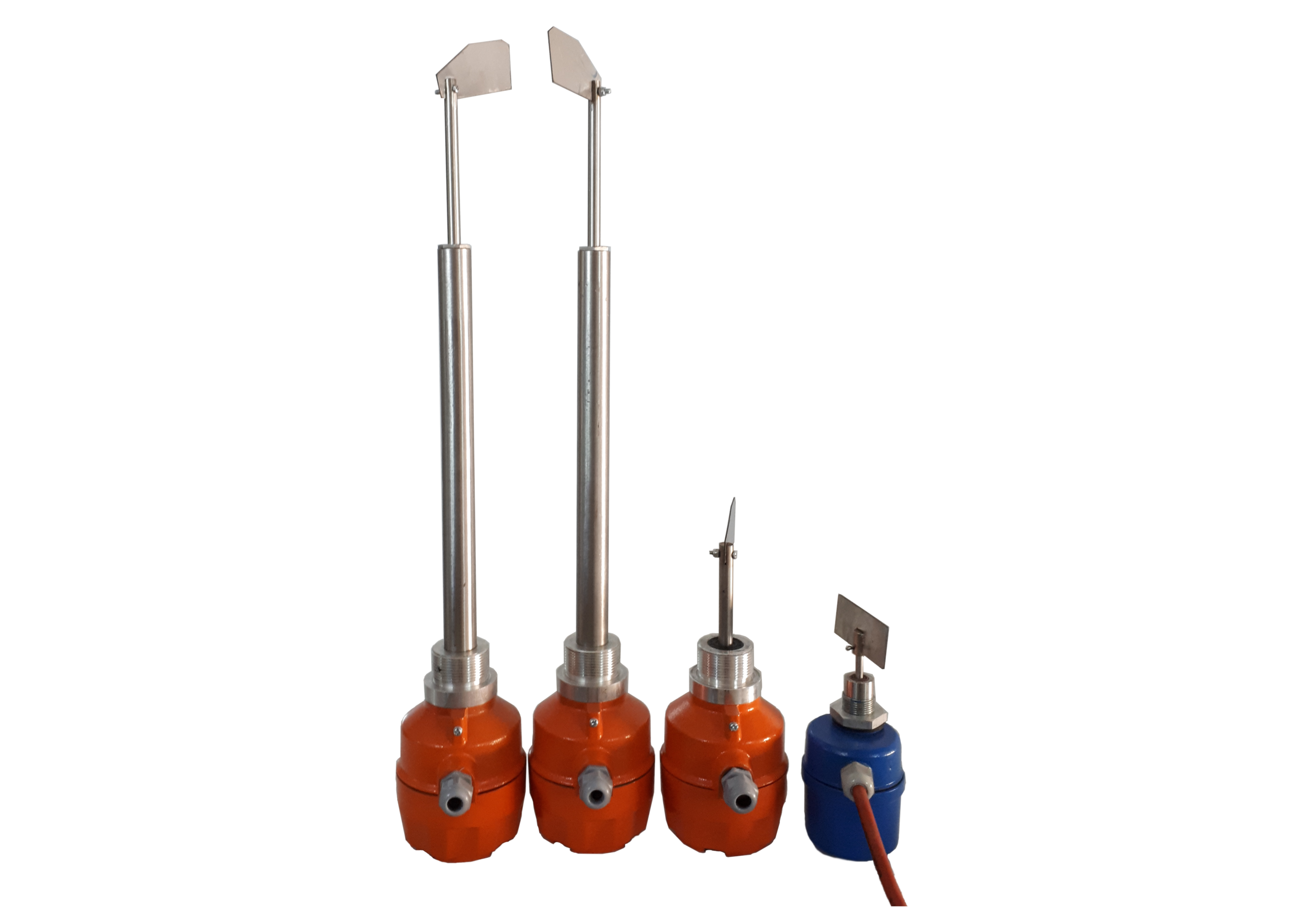
The device detects a defined level at its installation point; it does not continuously measure the contents of the vessel. Paddle shape, shaft length and mounting position are selected for the material and the required high or low level duty. The photographs show the compact blue unit and orange units with different shaft lengths.
FH1 and FH2 model configurations
The orange FH1 and compact blue FH2 (mini type) cover different mounting arrangements. Select the shaft and paddle for the installation point, bulk density and material flow; housing colour alone is not a specification.
| Supply options | 220 V AC or 24 V DC; specify the required supply for the ordered model. |
|---|---|
| Mounting and shaft | Top or side mounting, with shaft lengths from 10 to 100 cm. A cable extension arrangement can be reviewed for lengths over one metre. |
| Drive speed | 2 rpm for the described product configuration. |
| Housing and shaft | Aluminium housing with stainless steel shaft and sleeve in the described configuration. |
| Enclosure | IP65; confirm the enclosure and seals on the selected model and its nameplate. |
| Sensitivity | Spring adjustment of the operating torque to match the resistance of the material at the paddle. |
| Output delay | ON Delay and OFF Delay options; availability and adjustment range must be specified for the chosen model. |
| Control connection | The 220 V AC connection example uses COM, NO and NC switching terminals. Use the wiring diagram for the supplied unit to establish contact ratings and the interface to the control circuit. |
Confirm the supply, shaft length, process connection, output contact and available delay functions together before ordering a replacement. The 24 V DC unit must be wired from its own diagram.
Switching cycle and adjustment
When material arrests the paddle, the mechanism changes the signal switch and stops the drive. A spring or magnetic coupling protects the mechanism against overload, depending on the construction. Rotation resumes after the material releases the paddle.
Set sensitivity for the actual material, then check both the covered and uncovered states. During commissioning, confirm the signal at the PLC or control circuit, the selected high or low level duty, and the response after the material falls below the paddle.
Technical selection
| Material | Bulk density, particle size, flowability, moisture, adhesion and filling impact. |
|---|---|
| Mounting | Top or side position, connection, shaft length, paddle clearance and space for removal. |
| Electrical | Supply voltage, switch output, control connection and the required response on loss of supply. |
| Environment | Material and ambient temperature, dust, enclosure and any application specific protection requirements. |
Installation & maintenance
- Avoid direct impact from the filling stream and positions where material can bridge around the paddle.
- Check shaft movement, sealing and switching before relying on the signal in the control sequence.
- Review paddle build-up and free movement during planned maintenance.
Equipment photographs

Request a technical review
Send the application, operating conditions, dimensions and available drawings or photographs. State any information that is still unknown so the technical review can address it.