Industrial self-cleaning filters
Filtration systems that combine a separating element with a defined method for removing accumulated solids. Fluid properties, particle behaviour, operating conditions and the reject route determine which cleaning arrangement is suitable.
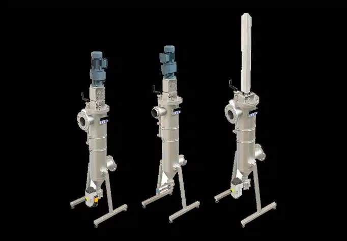
Operating principle and configuration
Particles accumulate on the filter surface during service. A mechanical scraper removes deposits by acting on the surface; suction and reverse-flow cleaning use different paths to carry contamination away. These arrangements are not interchangeable: viscosity, fibres, abrasive particles and deposit adhesion affect their suitability.
A cleaning cycle may start from differential pressure, a timer or an operator command. Differential pressure is measured across the filter, rather than being the pipeline’s pressure rating. Cleaning must remove the accumulated material through the reject line. Whether filtration continues during the cycle, and how much fluid is discharged, depends on the proposed configuration.
Main technical specifications for selection
| Fluid and contamination | Composition, viscosity at operating temperature, particle sizes and concentration, fibres, adhesion and abrasiveness. |
|---|---|
| Required separation | Target outlet quality, nominal slot or retention requirement and acceptable solids carryover; confirm performance with the actual feed. |
| Operating envelope | Normal and peak flow, operating and design pressures, temperature, available pressure drop and feed fluctuations. |
| Element and housing | Active area, flow direction, allowable loading during service and cleaning, compatible alloys, seals and required pressure design. |
| Cleaning mechanism | Scraper geometry and drive, suction or backwash arrangement; review contact or clearances and the behaviour of the retained solids. |
| Reject route | Discharge connection, back pressure, solids handling, disposal or recovery route and permitted loss of process fluid. |
| Control and utilities | Pressure measurement points, cleaning trigger, cycle timing, manual operation, alarms, power or compressed-air requirements. |
| Installation and scope | Connections, isolation and any specified bypass, service clearance, replacement element or complete package, and inspection documents. |
Technical arrangement
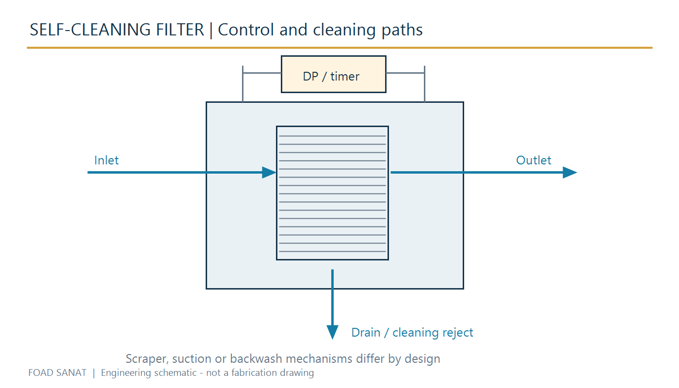
Installation, inspection and cleaning
- Record clean-filter differential pressure under known flow and temperature conditions as an operating reference.
- Check that a cleaning command produces the intended movement and reject discharge. Investigate rising residual pressure drop after repeated cycles.
- Inspect the element, cleaning member, seals and discharge valve at the planned service interval. Self-cleaning does not remove the need for maintenance.
- Before service, isolate, depressurize and drain the equipment according to the plant procedure. Keep space available for element and drive removal.
Related filter equipment
Request a technical review
Send fluid composition and viscosity, particle data, normal and peak flow, pressure and temperature limits, required outlet quality and reject-line conditions. State the available utilities and whether the request is for an element or a complete filter package.