Wedge wire vessel support grids
Internal slotted grids for supporting catalyst, resin or other granular media while allowing process fluid to pass. The screening panels and the load-bearing vessel supports must be specified as one coordinated arrangement.

Operating principle and configuration
A grid combines a media-retaining wedge wire surface with panel supports, frames and the vessel’s bearing points. Panels may be divided into segments for access through a manway and assembled on the support structure inside the vessel.
Media can escape through panel joints, edge gaps or penetrations as well as through the slots. The design therefore has to address retention across the complete assembled surface, together with bed load, differential pressure and the direction of possible uplift.
Main technical specifications for selection
| Vessel geometry | Internal diameter, support-ring level, beam positions, nozzles, penetrations and manway clear opening. |
|---|---|
| Media bed | Media type, grading, depth and dry and wet bulk density; identify any supporting layers. |
| Design loads | Media weight, differential pressure in each operating phase, permitted uplift and any agreed maintenance loading. |
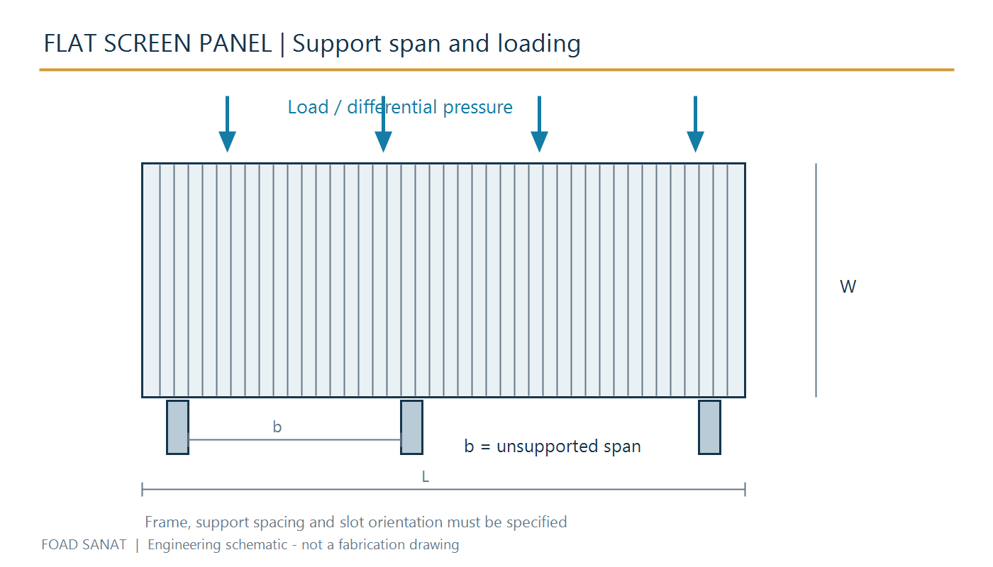
| Panel and slot | Nominal slot and tolerance, wire profile, support profile and spacing, active area and actual unsupported spans. |
| Segmentation | Panel layout, identification, installation sequence, lifting access and dimensions that pass through the manway. |
| Joints and edges | Joint gaps, perimeter retention, penetration details and sealing or overlap arrangements to limit media bypass. |
| Fixing and support | Bearing surfaces, clamps, bolts and positive retention; coordinate vessel-side supports and responsibilities. |
| Material and inspection | Process temperature, liquid or gas chemistry, cleaners and thermal movement; agreed checks for fit, welds, slots and material identification. |
Technical arrangement
Installation, inspection and cleaning
- Trial-check the numbered panel arrangement, bearing surfaces and fixings against the approved assembly drawing before media loading.
- Inspect panel joints, perimeter gaps and penetrations for paths that could release media.
- Keep the intended supports and load paths intact. Do not assume that the grid is a personnel platform or place maintenance loads on it unless that duty is explicitly approved.
- At shutdown inspect deformation, wear, corrosion, welds and loose fixings. Evaluate replacement panels with the original support span, loading and joint details.
Related filter equipment
Request a technical review
Provide the vessel internal drawing, ring and beam layout, manway opening, media grading and bed depth, dry and wet bed conditions, differential pressure, temperature, chemistry and the required scope of supply.